


“It’s kind of like 奥5 Sketch meets After Effects”
– A designer
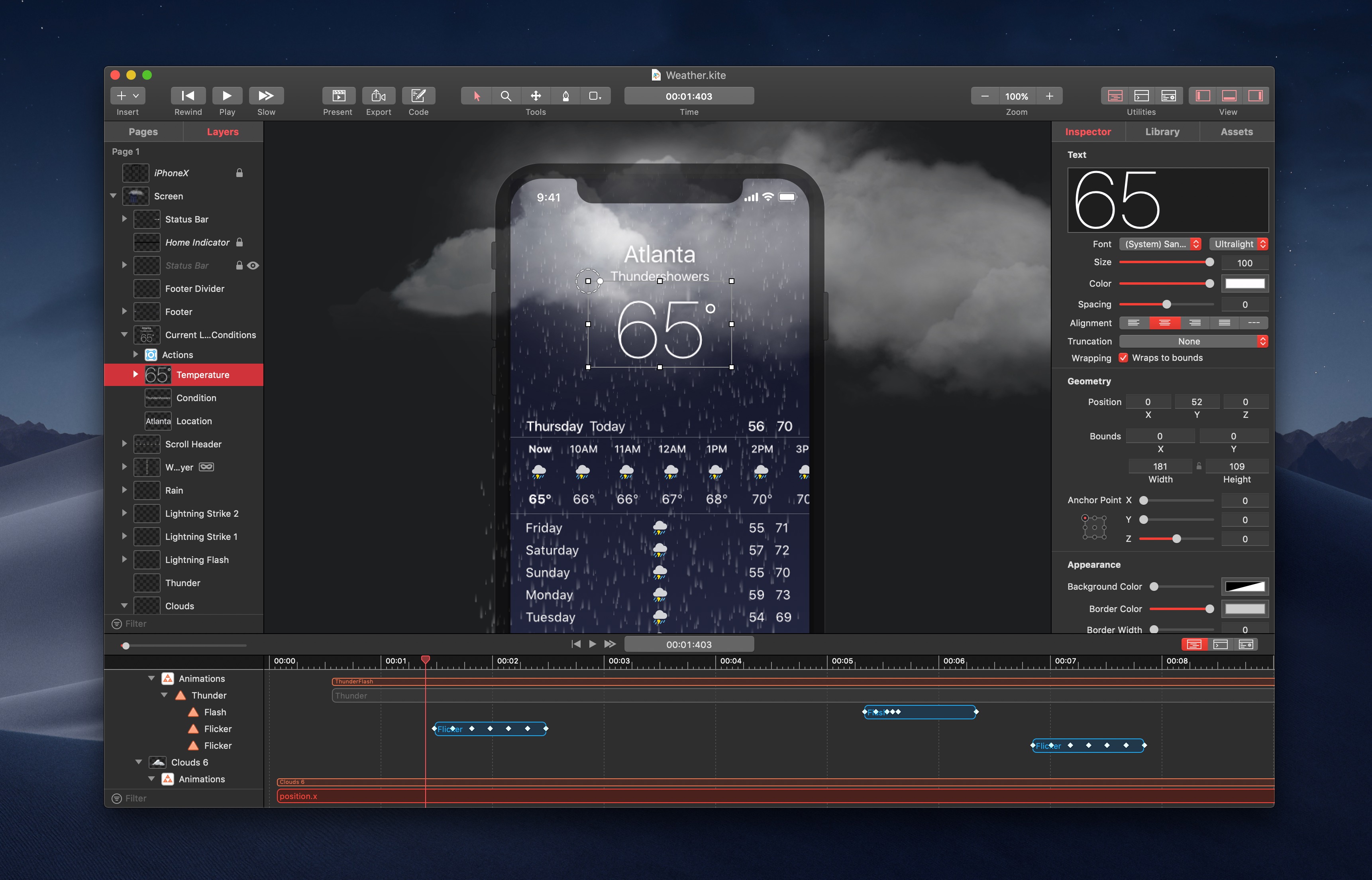
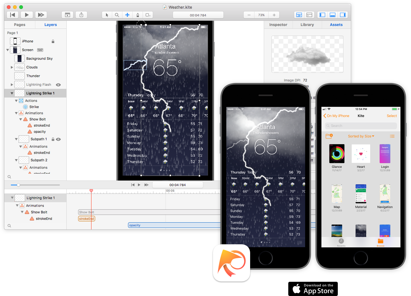
Visually drag and drop layers to build complex interfaces on a WYSIWYG canvas. Add animations and tune them with the integrated timeline.
Video
Have 1 minute? Watch a video.
“It’s kind of like PaintCode but for Core Animation”
– A developer
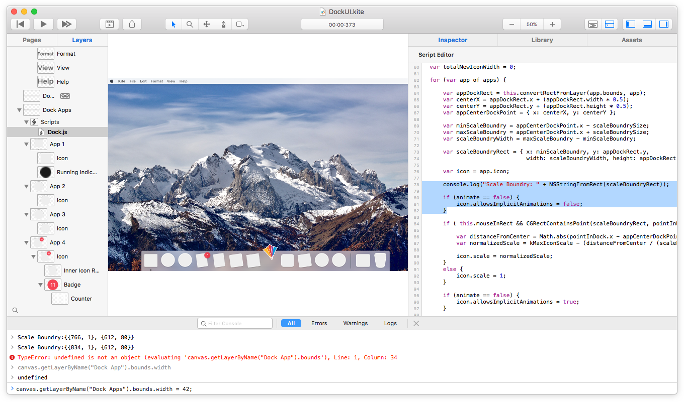
Use the built-in JavaScript scripting environment to enhance the detail of each interaction. Incorporate custom logic and behavior to achieve exactly what you need.
2024年澳洲游戏的幸运五168开始查询记录结果、实时更新走势图
2.1.2 – macOS Sonoma Fixes
An update to Kite is now available with fixes for bugs in the latest version of macOS Sonoma.
Read More →Keep up-to-date with the latest Kite news
Examples
Just a few examples of what you can create with Kite Compositor. You can explore all of these example documents and more from within the template chooser of the app.
See all examples ›
See more in the Showcase ›
奥5 Features
Kite is full of amazing tools and features to help you bring user interfaces to life quickly. See all features ›
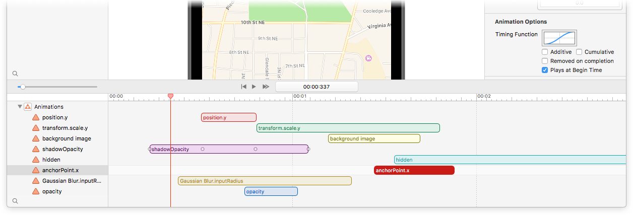
Timeline
The integrated smart timeline allows you to drag and edit animation durations and keyframes.
Snap animation start and end times together for a precise, hand-tuned feel.
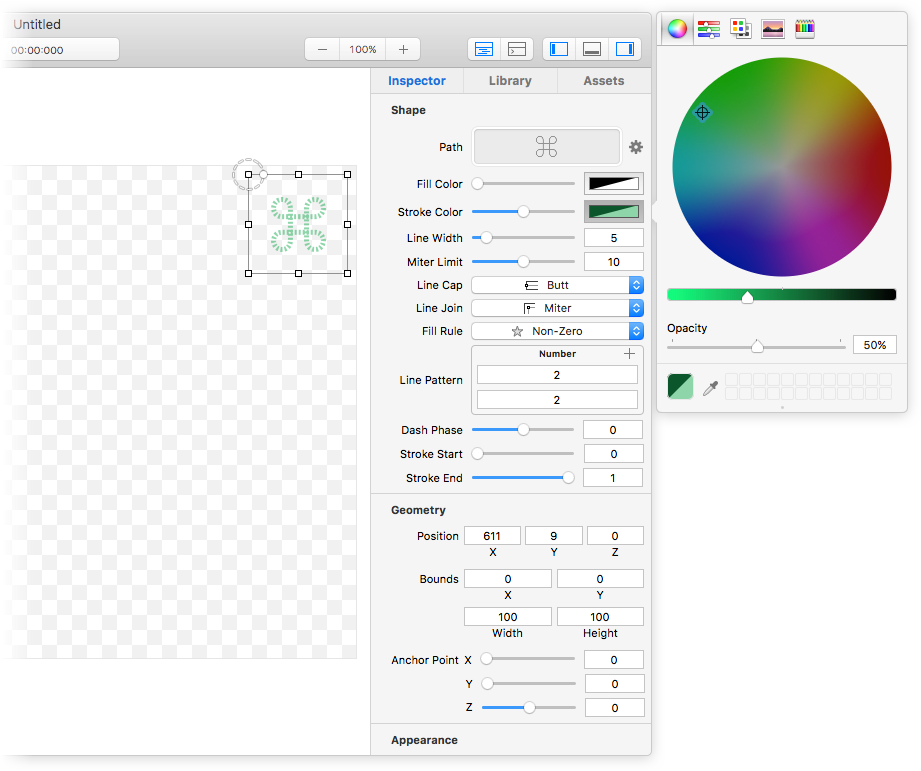
Inspector
A robust and powerful object inspector allows you to edit all of your layers’ properties in just a few clicks.
Set colors, adjust animation curves, add Core Image filters – all at the click of a mouse.
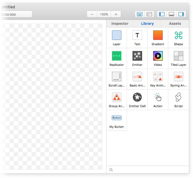
Library
Drag and drop layers and animations from the library to build your interface visually.
Save reuseable layer hierarchies into your library for easy component reuse.
e.g. “My Button”
Design on Mac → View on iOS
Are you ready to get a sense of how your designs feel on an actual iOS device? Download the native companion app, Kite Compositor for iOS.
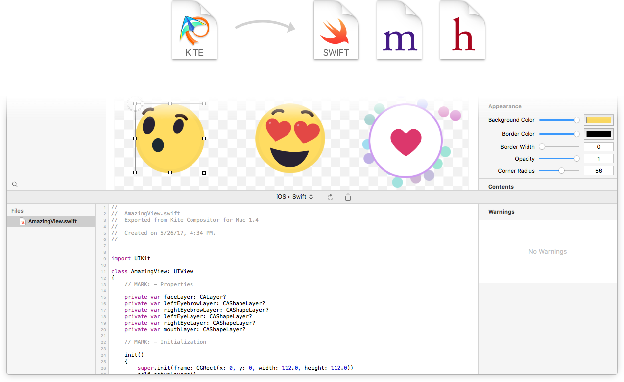
五分钟了解澳洲168的幸运5直播号码历史查询、历史结果、检索数据等!Generate Native Core Animation Code
Generate zero-dependency Swift or Objective-C code for your animation
Code compatible for both iOS and Mac
No more guessing how fast something should move, how large it should grow, or how to ease between keyframes
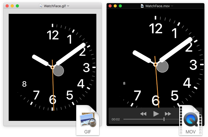
Export
Share your designs by exporting a video recording of your animation.
澳洲幸运5168官方历史记录查询、开奖记录结果号码体彩网 Scriptable
Add sophisticated logic to your animations and interactions via the built-in JavaScript scripting engine. Query and make live edits to your running animation from the built-in JavaScript console. Fire animations, add new layers, change properties and much more.

Built on Core Animation
澳洲行运五 Kite was built from the ground up for Mac using macOS's native Core Animation technology.
Core Animation is one of the key underpinning graphics technologies on Mac and iOS that produces stunning animations at high framerates.